Obivously most people who have followed the progress of this blog over the years would realise that it's becoming increasingly difficult to buy the Lexcom parts.
If anyone has any leads on where these components can still be purchased, please put a comment in on this post.
Cheers
Tuesday, July 22, 2014
Friday, August 29, 2008
Cables terminated
We are now at a stage where all the room outlet points have been terminated in the distribution panel, and we can start using the outlets. Currently we have some data points and some TV points connected.
Just to refresh your memory, we are installing the distribution cabinet inside an otherwise unused bulkhead in the house.
 ^ The distribution cabinet with the face panel now in place. You can see the white wire at the bottom left - that's the power supply lead to the panel which needs to be lengthened and then run through one of the punch out holes in the cabinet.
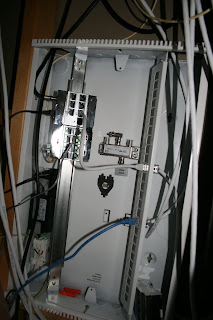
 ^ Looking up from the bottom towards the top of the panel, you can see I've put in a shelf. The LexCom room outlet wires are neatly bundled together. The extra cream cable is the telephone cable - it just needs to be gathered and tied for neatness.
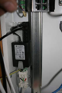
 ^ Here's the shelf - it has our ADSL modem/router/Wireless point. The ADSL input comes from the LexCom box, and there are two blue cables out - one goes directly to LexCom data switch in the cabinet, and the other goes direct to one of the room outlets.
 ^ Here you can see blue cable that goes directly to one of the room outlets. The two grey patch leads are for TV antenna, and the blue patch cable links the data switch to a room outlet.
 ^ This is the mess you are left with after terminating 24 room outlet cables.....
Just to refresh your memory, we are installing the distribution cabinet inside an otherwise unused bulkhead in the house.
 ^ The distribution cabinet with the face panel now in place. You can see the white wire at the bottom left - that's the power supply lead to the panel which needs to be lengthened and then run through one of the punch out holes in the cabinet.
 ^ Looking up from the bottom towards the top of the panel, you can see I've put in a shelf. The LexCom room outlet wires are neatly bundled together. The extra cream cable is the telephone cable - it just needs to be gathered and tied for neatness.
 ^ Here's the shelf - it has our ADSL modem/router/Wireless point. The ADSL input comes from the LexCom box, and there are two blue cables out - one goes directly to LexCom data switch in the cabinet, and the other goes direct to one of the room outlets.
 ^ Here you can see blue cable that goes directly to one of the room outlets. The two grey patch leads are for TV antenna, and the blue patch cable links the data switch to a room outlet.
 ^ This is the mess you are left with after terminating 24 room outlet cables.....
Wednesday, August 20, 2008
Cabinet installation
The 22 inch cabinet has now been installed into the planned space in the house. The front door comes off the cabinet, and there's a face plate which comes off to allow installation of components and power supply.
The power supply must be wired in by a licensed electrician. The mains power feeds into a small transformer, which then connects to a small distribution box. The picture below shows the transformer installed into the cabinet, and the small distribution block.
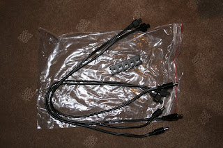
The picture below shows the power distribution block and the power leads before installation into the cabinet:
The cabinet has some holes in the side to allow you to screw it onto some studs inside a wall, and there are holes in the back if you want to mount it as a surface mount cabinet on a wall. There are also some knock out panels so you can choose where you want to feed your wires in.
Our cabinet is installed inside an empty bulkhead, and the cabinet is screwed to a stud on the side, and a noggin on the bottom. The space in the bulkhead is quite confined for taking photos, however you can sort of see it in the picture below:
The initial requirement was to have TV to one point, and broadband connection to the home office. In the picture above you can see that on the right of the box there are two cables plugged in - the top grey cable connects a wall outlet to the TV/Video module. The blue cable connects a wall outlet to an ethernet port on our ADSL modem/router, which is out of the picture.
The ADSL modem/router receives the phone line from the telephone module which is one of the silver components installed on the left side of the box.
The picture below shows a photo of the component currently installed in the box:
 The top module is the TV/Video distribution component - it's an active component requiring power and you can see the silver connector one the coax cable from the TV antenna, and the black power lead. You can see the grey patch cable which is referred to above.
The module below id the telephone distribution component. On the left (the green connectors) you can see the cream telephone cable connected. Elsrwhere in the house I have an ADSL splitter installed which provides ADSL on the red and black wires, and telephone on the white and blue wires. The telephone component allows configuration via some switches so that (in this case) I can ADSL on 4 ports, and telephone on 4 ports. These can be patched across to any wall outlet which needs them. I may change the configuration soon as I really only need the ADSL signal on one port, which is connected to the modem. You can see the grey wire which is running to my modem.
I hope this lot makes some sense! Now to connect more things!
The power supply must be wired in by a licensed electrician. The mains power feeds into a small transformer, which then connects to a small distribution box. The picture below shows the transformer installed into the cabinet, and the small distribution block.

The picture below shows the power distribution block and the power leads before installation into the cabinet:

The cabinet has some holes in the side to allow you to screw it onto some studs inside a wall, and there are holes in the back if you want to mount it as a surface mount cabinet on a wall. There are also some knock out panels so you can choose where you want to feed your wires in.
Our cabinet is installed inside an empty bulkhead, and the cabinet is screwed to a stud on the side, and a noggin on the bottom. The space in the bulkhead is quite confined for taking photos, however you can sort of see it in the picture below:

The initial requirement was to have TV to one point, and broadband connection to the home office. In the picture above you can see that on the right of the box there are two cables plugged in - the top grey cable connects a wall outlet to the TV/Video module. The blue cable connects a wall outlet to an ethernet port on our ADSL modem/router, which is out of the picture.
The ADSL modem/router receives the phone line from the telephone module which is one of the silver components installed on the left side of the box.
The picture below shows a photo of the component currently installed in the box:
 The top module is the TV/Video distribution component - it's an active component requiring power and you can see the silver connector one the coax cable from the TV antenna, and the black power lead. You can see the grey patch cable which is referred to above.
The module below id the telephone distribution component. On the left (the green connectors) you can see the cream telephone cable connected. Elsrwhere in the house I have an ADSL splitter installed which provides ADSL on the red and black wires, and telephone on the white and blue wires. The telephone component allows configuration via some switches so that (in this case) I can ADSL on 4 ports, and telephone on 4 ports. These can be patched across to any wall outlet which needs them. I may change the configuration soon as I really only need the ADSL signal on one port, which is connected to the modem. You can see the grey wire which is running to my modem.
I hope this lot makes some sense! Now to connect more things!
Friday, July 25, 2008
Wall plates - the installation
Decided to go through and fit off some of the wires with the connectors and wall plates. The starter kit provides everything you need and includes some pretty decent instructions, however I've also taken my own photos (below). Hope you find them useful!
 The above picture shows the hole cut in the wall where the hanger was located prior to the plaster going on. If you are putting these in yourself, make sure you put marks on the floor so you can find the right spot - all of our hangars were centred 300mm in height from the floor.
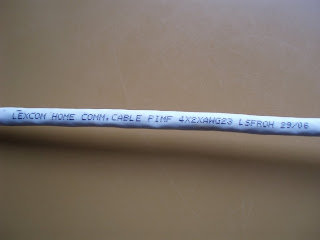 Here's a close up of the markings on the LexCom cable
 After pulling the cable through, strip off 5 cm of the outer cover - revealing the shield.
 Pull the shield back.
 Separate the 3 pairs of wires
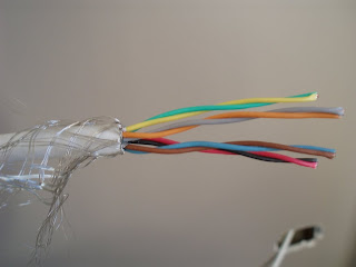 Strip off the shield from each pair of wires
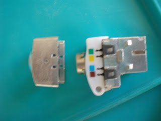 The connector comes in two parts
 Slide the cover over the cable and push it past the braid
 Open the connector - note the colour coding on one side
 ... and the colour coding on the other side
 Push the connector over the coloured wires
 Now seat each of the wires into the correct slot, making sure to follow the guide pins
 Another view
 Now firmly close the connector - push hard until you hear the click. The connector automatically cuts into the wires with the pins.
 Trim the excess wire close to the connector
 Trim the braid (Shielding) and slide the cap on until it clicks into place
 This shot shows the connector installed in the wall plate, before the cover plate is clipped in place.
 Wall plate cover in place
The next series of photos show what I did with the wall plates.
 Wall plate come with one small plastic pop-off, under which you can put an identification number. I printed numbers for each port using the label maker.
 You can see the small place for the number above the connector hole
 Numbers in place on the 4-port wall plate
 Numbers on the two port plate - note the adapter which goes into each plate. The connector clips into the adapter.
Each of the wall plates also has a cover plate which is clipped onto the wall plate after the wall plate is screwed onto the wall.
Tuesday, July 22, 2008
Starter Kit
The next step in the LexCom installation was to purchase the distribution panel - the 22 inch panel can accommodate up to 26 points, the 14 inch panel can accommodate up to 18 points.
Given that we have now wired 24 points around the house, the 22 inch panel is the go!
It's possible to purchase all components separately, however LexCom do provide a starter kit which makes it a little easier to get the core components.
Cost of the starter kit (RRP retail) is a whopping $2048 including GST. Fortunately, my sparkie has a trade account with the wholesaler and I was able to buy the kit at trade price.
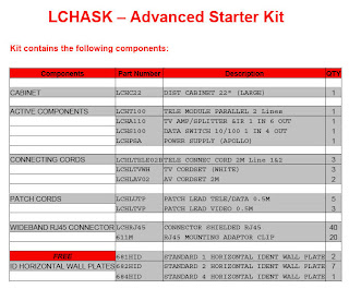
Starter kit components:
 Starter Kit Box
 Starter Kit Contents
Given that we have now wired 24 points around the house, the 22 inch panel is the go!
It's possible to purchase all components separately, however LexCom do provide a starter kit which makes it a little easier to get the core components.
Cost of the starter kit (RRP retail) is a whopping $2048 including GST. Fortunately, my sparkie has a trade account with the wholesaler and I was able to buy the kit at trade price.
Starter kit components:

 Starter Kit Box
 Starter Kit Contents
Monday, July 21, 2008
Wiring
This blog post goes through the process we went through to pre-wire the new home we are building with the LexCom cable.
Important note: PDL will provide a warranty providing the network is installed and certified by a licensed installer.
First of all, we bought a roll of the LexCom CAT7 cable from an electrical wholesales. The drum of cable is 300 metres long, it's part number is LCHC300, and it cost a whopping $748 including GST. That was the full retail cost from one particular supplier as at March, 2008. If you are using an electrical installer or authorised LexCom installer, then the installer may pass on a trade discount.
Why is it so expensive? Because it's a high capacity double shielded cable, with a frequency range of up to 900 MHz, that exceeds the frequency currently used for free to air analogue and digital television. The data components exceed the current CAT 6 data specification. So now you know!
So, armed with our drum of the world's most expensive cable and the wiring diagram we put together, we started running cables from the place where our central distribution panel would be installed, to each of the rooms where we wanted outlets.
 White cables are the LexCom cables
 Distribution box will be in this cupboard
 Phone, TV and LexCom cables all come in here
The cabling took half a day, and consisted of running cables from the distribution point to all the rooms. We even put one into the al fresco area, in case we decide to put a TV out there at some stage.
Each cable was numbered (we wrote in pen on each end of the cable) and the wall fixings were installed where the cables will be terminated on a wall plate:
 The picture above shows three LexCom cables through the hanger - the face plate will eventually be screwed into the hanger.
As well as writing on the actual cables, we also marked the concrete or timber floor with the numbers to make it easier to find the cables after the plaster is on. The centre of each hanger is 300mm from the floor, and is marked with a line (as shown below)

The only exception to the 300mm rule is for a cable which might be higher for a wall mounted TV, or the al fresco cable which will be in the ceiling.
Planning your network
The first thing you need to do after deciding that the LexCom system is the right one for you, is to plan out where everything is going to go.
You can check the Technical Installation Guide elswhere on this site, but a few points are list below which may help:
We are building the Porter Davis Cremorne 41, which is a double storey home. The plans we drew up for the network points are provided below:
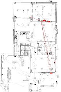
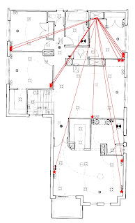
The distribution box lives on the first floor, to the rear of the house (there's an empty bulkhead net to a wardrobe which can be used to house the panel.
In our network there are 11 points downstairs, and 12 points upstairs - making a total of 24 points. The 22 inch cabinet can accomodate up to 26 points, so that's what will go in.
Hope this helps!
You can check the Technical Installation Guide elswhere on this site, but a few points are list below which may help:
- Where are you going to install your distribution panel?
- Plan to run your phone line, data line and TV antenna into your panel.
- Which rooms do you want the telephone patched into (not many in our case, as we have some cordless handsets we will use)
- Which rooms do you want data available in? Will you need more than one data port (for example, a network printer and a PC)?
- Which rooms do you want TV or video signals available in?
We are building the Porter Davis Cremorne 41, which is a double storey home. The plans we drew up for the network points are provided below:


The distribution box lives on the first floor, to the rear of the house (there's an empty bulkhead net to a wardrobe which can be used to house the panel.
In our network there are 11 points downstairs, and 12 points upstairs - making a total of 24 points. The 22 inch cabinet can accomodate up to 26 points, so that's what will go in.
Hope this helps!
Subscribe to:
Posts (Atom)


